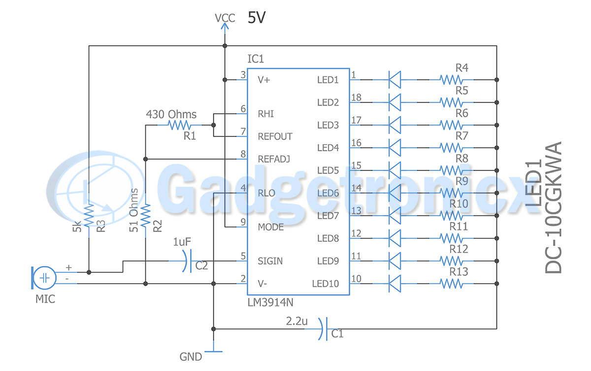
Step by step guide Circuit Diagram An Audio Level Indicator (VU meter) or volume unit meter, are electronic devices that display the intensity of any Input audio signal, usually in musical pieces of equipment (Drum sets, mic, electric guitars, amps, speakers, etc.). More specifically, it helps to visualize analog signals. The audio level meter is a circuit that detects and measure the level of audio/sound in the surrounding. These sound circuit converts sound energy from the surrounding into electrical energy to light LEDs accordingly. A number of transistors, LEDs, and an electret mic make up the sound/ audio level meter.

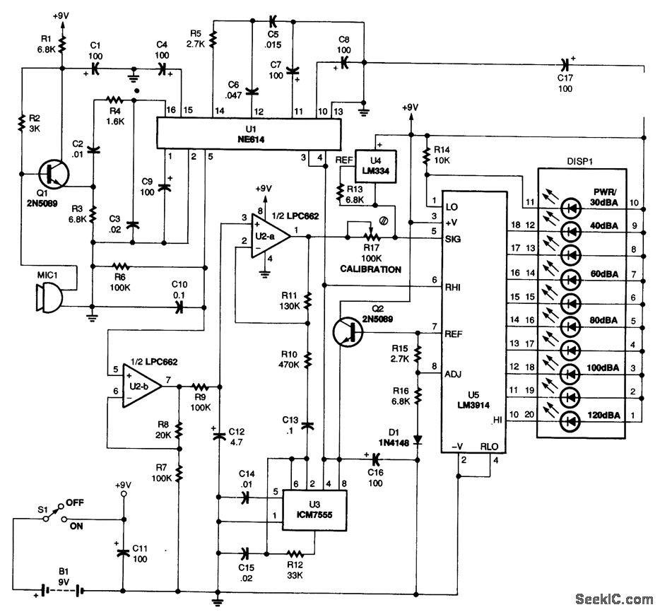
Circuit Diagram: Circuit for this Arduino Sound Level Meter is a very simple in which we have used the LM386 Audio amplifier circuit to amplify the signals from a condenser microphone and supply it to the Analog port of Arduino. We have already used this LM386 IC to build a low voltage audio amplifier Circuit and the circuit more or less remains the same. Sound Level Meter With Arduino: Previously three different versions of Sound Level Meter (From hereinafter as SLM) circuits are introduced. All these circuits are mainly utilizing op-amps (NE5534, TL071) and LM3915 bar/dot display driver IC. Also, the MIC, pre-amplifier, and LM3915 circuits are closely hardwired, any change of circuit

StefanoMastella/DIY_MEMS_SPL_Meter: A low Circuit Diagram
Use the code 'SPL_Meter' to calculate and plot the sound pressure levels. Change the folder path to the one you want to analyze. To calibrate the device one can use a commercial calibrator along with a coupler for the MEMS microphone, use the calibration signal available in the 'Bkgn Meas 01' folder (but only if one uses the same microphone model I did), or use the sensitivity value to adjust
As Mic is completely isolated from any other audio signal processing circuits, this sound level meter does not interfere with any audio signals between PC and power amplifier. But capturing adequate sound pressure level becomes an important matter to make a dynamic visual effect by LM3915.
Another Sound Level Meter Circuits : 4 Steps (with Pictures ... Circuit Diagram
1 const int micPin = A0; // Pin A0 is used for the microphone input 2 3 int sample; // Variable to store the current sound sample 4 int maxVal = 0; // Variable to track the maximum sound level detected 5 int minVal = 1023; // Variable to track the minimum sound level detected 6 7 // Shift register pins 8 int LatchPin = 3; // Pin 3 is connected
Among the two SLM variants, the miniature version's schematics are the exactly same as the prototype version. But the other variant (I'll call this new device as MIC/Display modules version) uses the same schematics with divided circuit modules and their connection with the USB cable as shown in the picture above.